
Management - Vlan 10: 192.168.10.0/24
Guest - Vlan 30: 192.168.20.0/24
It is assumed that we have vlans in the form of vlans and the necessary switch configuration.
On the interface screen, click on the Network->Interface menu. On the screen that opens, go to the Vlan tab.
Let's start configuring the MANAGEMENT VLAN settings by clicking Add.
On the screen that opens, we fill in the relevant fields as in the image.
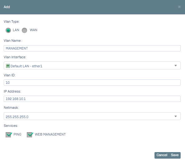
After saying Save, we configure the GUEST VLAN settings by clicking Add again.
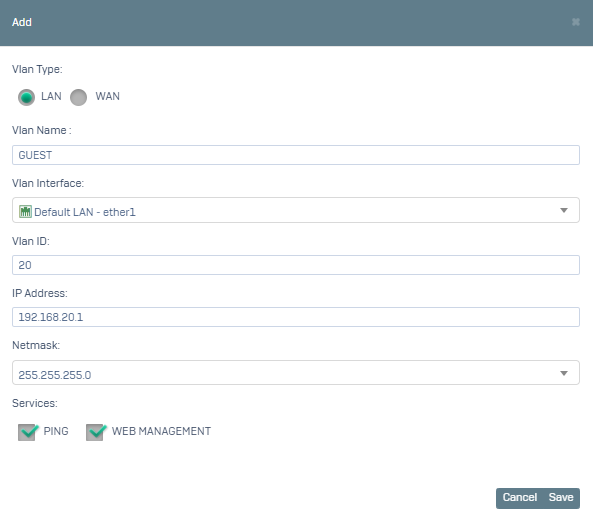
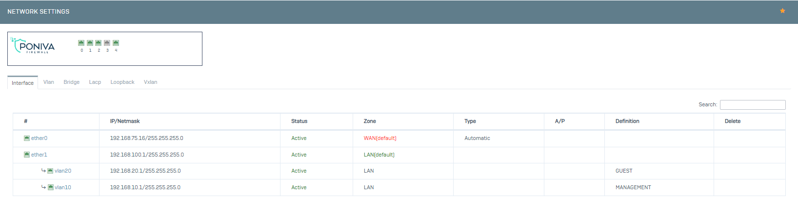
Save and our VLAN configuration is complete. Our VLAN definitions are displayed on the Interface screen as follows.
Now we start configuring DHCP settings.
On the interface screen, click on the Network->DHCP menu.
Click on the Add option.
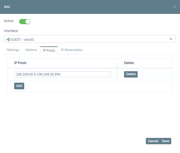
The service is activated on the screen that opens. Interface (select the relevant vlan definition), go to the IP Pool tab and define the IP pool here. When adding a VLAN definition, we set IP/Netmask 192.168.10.1/255.255.255.255.0 for management and we need to configure the IP pool accordingly.
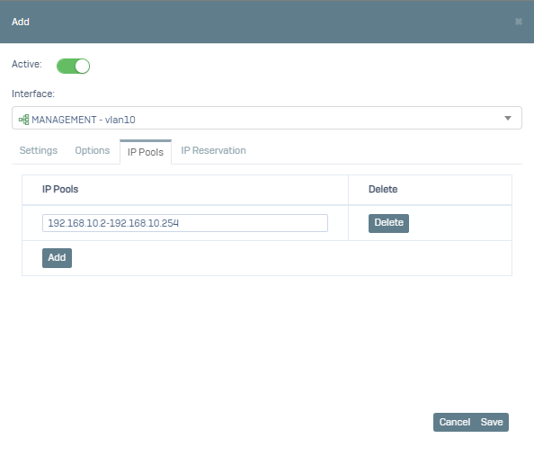
After saying Save, we do the same for the Guest Vlan.
The VLAN settings on the Poniva side are complete.